Video cameras are used in occultation work to create light curves showing the reduced light from a star as an asteroid passes in front of it. Although these events can have a binary on/off nature, sometimes the curves are more complicated and require interpretation in the context of noise. Furthermore, sometimes the intensity is interpreted quantitatively to estimate magnitude changes. Finally, grazing occultations can have complex light curves showing diffraction effects that can be quantitatively fit to a model. Even the time of an event can be affected by gamma, when transition events are present in the light curve and used for time interpolation. Most of the quantitative work assumes the video signal is linear with the light signal, but analog video cameras commonly have a gamma term applied. In this write up I describe the results of one way to measure the nonlinearity due to the gamma term, and I describe its impact on light curves.
"Gamma" refers to an intentional distortion of the video signal when it is converted to voltage or binary values. The voltage out is given by the detector signal raised to the power of gamma, where gamma is typically in the range from 0.4 to 2.5. This conversion is usually followed later by an inverse process of conversion with an opposite gamma that roughly restores the linearity. Assuming no additional noise sources or digitization error, the encoding by one gamma and decoding with its inverse value should restore the signal losslessly.
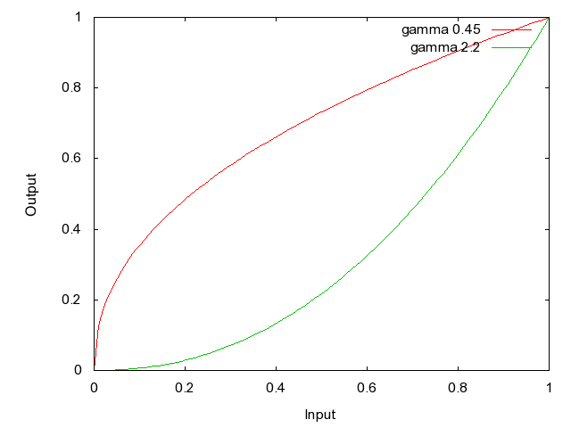
Schematic view of the effect of gamma on an input, for values of 0.45 and 2.2. Gamma=0.45 boosts the weak signal dreamatically, along with its noise, while gamma=2.2 supresses the weak signal and is more sensitive to changes in the high signal. 0.45 is approximately 1/2.2, so encoding with 0.45 then decoding with 2.2 will reproduce the original linear signal
Measuring gamma is simple in concept but nontrivial in practice. In theory all you need is a linear light signal that steps uniformly, and you just measure its intensity on a video camera to determine the light curve. In practice, such a linear light source is not readily available because any steady light may cause the source to heat up and drift over time. Plus, you would need a way to set the intensity of the light to known values.
Here are some approaches to making a calibrated light source:
- Use a microcontroller coupled to a DAC to produce a ramped current into an led at low power
- Use a microcontroller to provide brief pulses of light of varying duty cycle to simulate changing intensity
- Use an astronomical artificial star with calibrated settings at one magnitude increments
I have tried all three approaches and they all work to some degree. The artificial star uses a simple resistor ladder that provides roughly one magnitude steps, but the intensity drifts a bit at constant power. The DAC approach works well but requires the LED operate in a linear regime, and has added complexity with the DAC. For this write up, I used the pulse/duty cycle approach, which is very simple to code on a PIC microcontroller and requires no special timing other than the specification of the pulse duration on the microsecond scale.
I used a PIC18F4550 microcontroller operating at 48MHz, providing an instruction step time of 0.012 microseconds. This allowed good control of the pulse duration over the range of 1 to 256us, in tick times of 300 us as shown below.
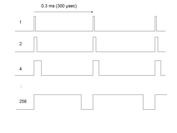
Sketch of the pulse pattern with changing duty cycle to simulate intensities with values 1, 2, 4 .. 256. Each tick period is 0.3ms, allowing roughly 50 ticks to fit within a 17ms video field at 60 fps. The ticks cannot be too large or they will appear with partial overlap in a video field, producing some variation in the intensity.
I then imaged the stepped LED with a PC164C-EX2 video camera in very dark conditions so that the camera remained in its "low light" mode that increases sensitivity, but produces ugly, striated stars. See my other write up on this. I recorded directly to disk via a Dazzle DVC90 capture card with default settings into VirtualDub. I then recorded the light curve with LiMovie using a fixed aperture and different settings of gamma within LiMovie. Note that you cannot take the light curve first and then undo the gamma because the individual pixel values must be gamma converted prior to summing within the aperture. The results are as follows:
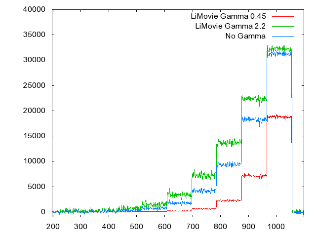
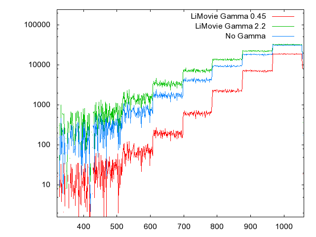
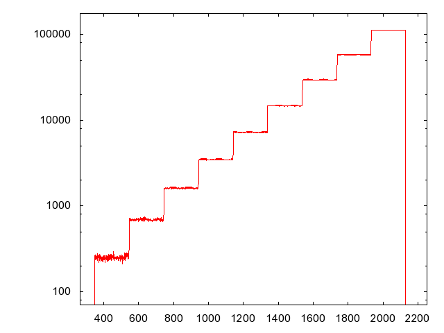
Plots of the LED intensity recorded by the PC164C-EX2 video camera. Upper plot is linear and the bottom is log. The intensity should be stepping by factors of two, which means it should appear linear on the log scale. Note that in the lower figure (log) the blue curve with no gamma applied shows proportionally smaller steps with higher intensity. This corresponds to having been recorded with a gamma<1. When I used an LiMovie gamma of 0.45 (red curve) the steps become much more uniform, suggesting the video camera has a gamma value near 0.45. Also note in the linear curve that this gamma correction results in a cleaning up of the noise at low intensities. In the linear plot, the blue, uncorrected curve, shows a fairly uniform level of noise across intensity, while the corrected curve (red) shows noise that increases with intensity - more in keeping with Poisson-like behavior.
Not all cameras have a fixed, non-unity gamma, however. I have a USB camera intended for scientific astronomical use: a Lumenera SKYnyx 2-0m. It has full control over exposure, gain, gamma and more. I used this camera with the stepped LED source and recorded with LucamRecorder direct to disk using gamma=1. The results are as follows:

Plots of the LED intensity recorded by the Lumenera SKYnyx 2-0m USB video camera. As above, the upper plot is linear and the lower plot is log. The uniformity of the steps in the log plot is evident, indicating that the gamma value is very close to 1.0. The steps near low intensity are a bit large, but that may be due to a slightly incorrect background subtraction. The fact that a linear USB camera gives a nice linear result for the stepped LED is evidence that LED is, in fact, stepping as designed
CONCLUSION: When using any video camera, be careful doing quantitative work because there may be assumptions of linearlity that do not hold. I think that most video cameras for consumer use will have a gamma in this range of 0.45, and LiMovie seems effective at linearizing the video by entering the value 0.45 directly and selecting the "gamma correction" checkbox. But unknown cameras should be checked by methods similar to the above to measure the gamma value directly. This will allow more accurate estimations of magnitude changes, and even timings will be more accurate when using an intermediate value in a light curve to interpolate the transition time.
Occultation and Video Timing Projects
Back to MetaGuide main site and forum
Questions, comments, join the forum at https://www.smallstarspot.com/